EXAIR’s Adjustable E-Vac® is a series of low cost, compressed air powered vacuum generators with vacuum and flow rates that can be easily adjusted to suit the application requirements. This small vacuum pump is ideal for a wide variety of pick and place, box opening, clamping, lifting, chucking, and surface mounting applications. The Adjustable E-Vac is maintenance free and has no moving parts to wear out. Engineered for high efficiency, this high vacuum pump minimizes compressed air use by allowing it to be tuned to the application. With a simple turn of the venturi unit, the vacuum and flow levels can be changed to overcome porosity and increase or decrease the lifting power. To meet the demands of many types of lifting jobs, EXAIR offers a large selection of vacuum suction cups to be used with E-Vacs.
EXAIR offers a variety of mufflers, tubing, check valves, and fittings that make it easy to build a vacuum system best suited to your vacuum application. In addition to these E-Vac vacuum generator accessories, there are other items that can help with the preparation and control of the compressed air.
When using E-Vac vacuum generators, it is important to use a source of clean, dry compressed air that will keep them operating at their peak performance. Automatic drain filter separators to keep the compressed air free of contaminants and moisture are recommended. Oil removal filters that remove oil particulate that is common to many compressed air systems are available. Pressure regulators, shutoff valves, compressed air hose, fittings, and solenoid valves (to electrically turn the compressed air on and off) are available as well.
Mufflers Optional silencing mufflers are available that permit maximum exhaust of the E-Vac unit so cycle speed is not reduced. The Standard Muffler (for use with In-Line E-Vacs only) has a closed end and is suitable for applications that are free of dust and debris. The Straight Through Muffler is recommended where particulate is present since it will not accumulate debris that can erode performance. Straight Through Mufflers offer the best sound level reduction (up to 26 dBA).
Fittings and Tubing
The vacuum port of the E-Vac has an NPT thread (a vacuum cup can be threaded directly into it). For vacuum cups that are remotely located, push-in connector fittings (most have global threads for use with NPT and BSP) can be installed on the E-Vac and the vacuum cup. Polyurethane vacuum tubing is available (10', 20', 30', 40' and 50' lengths) to connect them. For best performance, the length of the tubing should be minimized to achieve the best attach and release times.
Check Valve
A vacuum check valve is available to hold the vacuum in case of compressed air loss. It is designed for high flow so it doesn’t restrict airflow or slow the vacuum operation. Maximum vacuum can still be achieved without affecting the performance. E-Vac vacuum generators that are used without a check valve will release the load if there is a significant drop in compressed air pressure or the supply of compressed air is lost.
Adjustable E-Vac is available in 4 sizes that have adjustable vacuum rates up to 25" Hg (85 kPa) and flow rates up to 81 SCFM (2,294 SLPM). Kit configurations that include vacuum cups, fittings, tubing and a mounting clip are available
Choose the E-Vac by the SCFM (SLPM) flow that best suits the performance needed for your application.Adjustable E-Vac Kits give you the ability to experiment with an assortment of Vacuum Cups. E-Vac Kits include a Muffler, an assortment of (4) pairs of Vacuum Cups (closely matched to the performance of that E-Vac), (2) straight, (2) elbow and (1) tee vacuum fittings, 10' of vacuum tubing and a mounting clip.
Deluxe Kits include the same items as the standard kit with the addition of an automatic drain filter separator for the compressed air supply and pressure regulator (with coupler).
Set The Vacuum And Flow To The Application Requirements
Adjustable E-Vac vacuum generators are ideal for applications where a variety of vacuum levels are required, which is often the case when lifting a variety of materials. The amount of vacuum flow is easy to adjust. Simply loosen the lock ring by turning it counterclockwise, then, turn the exhaust of the Adjustable E-Vac to increase or decrease the flow. Once the desired level of vacuum and flow are obtained, the lock ring can be tightened to hold that setting. Tuning the vacuum and flow to the application requirements will help to minimize compressed air use.
Adjustable Vacuum Generator Performance
The amount of vacuum created varies with the porosity of the load being picked up. Units come from the factory set to 15" Hg (51 kPa). A maximum of 25" Hg (85 kPa) can be achieved on a solid, non-porous surface, but will require increasing the air consumption and vacuum flow.
Adjustable Vacuum Generator Performance
15" Hg (factory setting)
Model
Air Consumption
SCFM @ 80 PSIG
Sound Level in dBA
Vacuum Flow SCFM vs. Vacuum Level “Hg
(Set to 15" Hg)
No Muffler
Straight Through
Muffler
0
3
6
9
12
15
840008
8.2
89
77
5.80
4.68
3.71
2.59
1.53
0.00
840015
15.4
95
77
18.70
16.00
12.02
7.75
4.05
0.00
840030
26.4
99
74
36.70
32.00
25.63
17.68
7.69
0.00
840060
62.7
107
85
81.00
67.00
56.33
29.00
11.13
0.00
Adjustable Vacuum Generator Evacuation Time
15" Hg (factory setting)
Model
Evacuation time in seconds for a 1 ft. container down to listed vacuum (Set to 15"Hg)
0
3
6
9
12
15
840008
0.00
1.20
2.42
4.46
8.40
26.35
840015
0.00
0.53
0.97
1.60
2.83
8.30
840030
0.00
0.42
0.67
1.05
1.75
6.72
840060
0.00
0.42
0.66
0.91
1.37
4.10
Adjustable Vacuum Generator Performance
25" Hg ( max setting)
Model
Air Consumption
SCFM @ 80 PSIG
Sound Level in dBA
Vacuum Flow SCFM vs. Vacuum Level “Hg
(Set to 25" Hg)
No Muffler
Straight Through
Muffler
0
3
6
9
12
15
18
21
24
25
840008
12.2
104
89
5.80
5.58
5.18
4.80
4.33
3.83
2.94
1.93
0.37
0.00
840015
25.9
107
89
18.00
16.53
15.70
14.18
12.13
8.98
5.65
2.69
0.55
0.00
840030
44.8
107
82
32.00
29.00
26.83
24.12
20.92
14.63
9.90
6.13
1.19
0.00
840060
105.2
114
92
77.00
66.33
62.33
55.50
45.00
30.67
18.37
8.38
2.10
0.00
Adjustable Vacuum Generator Evacuation Time
25" Hg (factory setting)
Model
Evacuation time in seconds for a 1 ft. container down to listed vacuum (Set to 25"Hg)
0
3
6
9
12
15
18
21
24
25
840008
0.00
0.88
1.63
2.56
3.86
5.56
8.18
13.03
29.08
43.52
840015
0.00
0.57
0.93
1.40
2.00
2.83
3.90
6.77
14.87
29.33
840030
0.00
0.53
0.75
1.02
1.35
1.92
2.58
3.90
9.63
25.38
840060
0.00
0.35
0.53
0.73
1.00
1.33
1.88
3.02
8.93
22.07
Adjustable Vacuum Generator Performance - Metric
51 kPa ( factory setting)
Model
Air Consumption
SLPM @ 5.5 BAR
Sound Level in dBA
Vacuum Flow SLPM vs. Vacuum Level kPa
Set to 51 kPa
No Muffler
Straight Through
Muffler
0
10
20
31
41
51
840008
232.2
89
77
164.2
132.6
105.0
73.4
43.2
0.0
840015
436.1
95
77
529.5
453.1
340.3
219.4
114.7
0.0
840030
747.5
99
74
1039.2
906.1
725.8
500.5
217.8
0.0
840060
1775.4
107
85
2293.6
1897.2
1595.1
821.2
315.3
0.0
Adjustable Vacuum Generator Evacuation Time - Metric
51 kPa (factory setting)
Model
Evacuation time in seconds for a .03 cu. meter container down to listed vacuum
Set to 51 kPa
0
10
20
31
41
51
840008
0.00
1.20
2.42
4.46
8.40
26.35
840015
0.00
0.53
0.97
1.60
2.83
8.30
840030
0.00
0.42
0.67
1.05
1.75
6.72
840060
0.00
0.42
0.66
0.91
1.37
4.10
Adjustable Vacuum Generator Performance - Metric
85 kPa (max setting)
Model
Air Consumption
SLPM @ 5.5 BAR
Sound Level in dBA
Vacuum Flow SLPM vs. Vacuum Level kPa
Set to 85 kPa
No Muffler
Straight Through Muffler
0
10
20
31
41
51
61
71
81
85
840008
345.5
104
89
164.2
157.9
146.5
135.9
122.5
108.3
83.2
54.5
10.5
0.0
840015
733.4
107
89
509.7
467.9
444.6
401.4
343.3
254.1
160.0
76.1
15.6
0.0
840030
1268.6
107
82
906.1
821.2
759.8
682.9
592.3
414.1
280.3
173.7
33.8
0.0
840060
2978.8
114
92
1982.1
1878.3
1765.0
1571.5
1274.2
868.4
520.1
237.4
59.5
0.0
Adjustable Vacuum Generator Evacuation Time - Metric
85 kPa (max setting)
Model
Evacuation time in seconds for a .03 cu. meter container down to listed vacuum
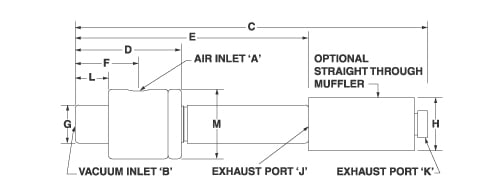
Compressed air flows through the inlet (1), then through a single directed nozzle (2). As the airstream exhausts, it expands and increases in velocity prior to passing through the venturi (3). A vacuum inlet tangential to the primary airflow (4) is located at the suction point between the orifice and the venturi. The airflow that is drawn through the vacuum inlet mixes with the primary airstream, then exhausts on the opposite end (5).
The amount of vacuum flow can be adjusted. When facing the exhaust end, loosen the lock ring (turn counterclockwise), then turn the exhaust. To increase flow, turn the exhaust counterclockwise. To decrease flow, turn the exhaust clockwise. Be careful not to unthread the exhaust completely. There will be a point where no more vacuum flow can be achieved.
The amount of vacuum created varies with the porosity of the load being picked up. Units come from the factory set to 15” Hg if used on a solid, non-porous surface. A maximum of 25” Hg can be achieved on a solid, non-porous surface, but will require increasing the air consumption and vacuum flow.